🔬 Research Projects
Investigating advanced optical cavity alignment, laser interferometry loops, and computational electro-optic modulation systems for next-generation physics detectors.
1. RF Jitter Alignment Sensing vs. WaveFront Sensing Schemes
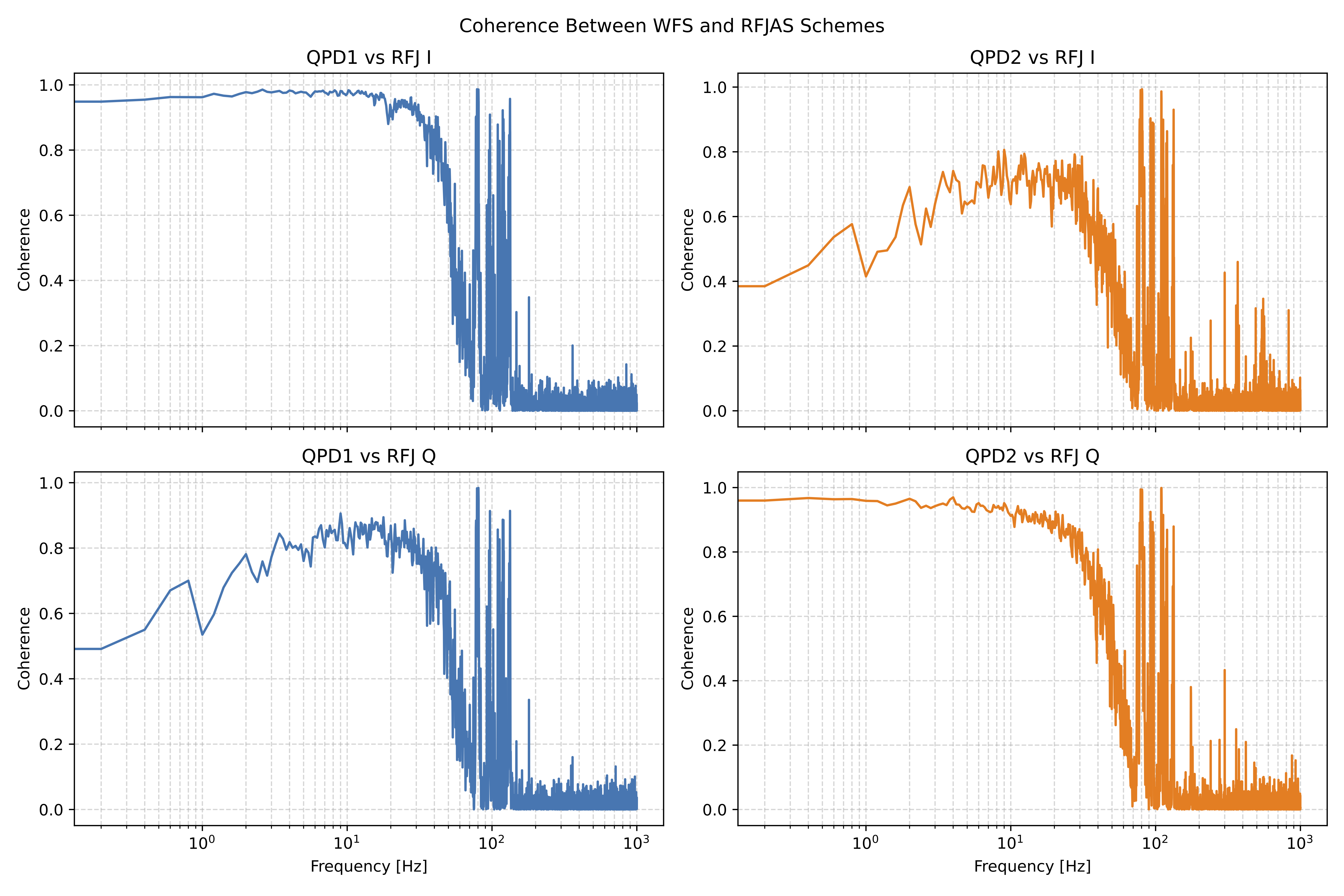
Precise laser alignment in optical cavities is essential for high-precision laser interferometry. We report on a table-top optical experiment featuring two alignment sensing schemes: the conventional Wavefront Sensing (WFS) scheme which uses quadrant photodetectors (QPDs) to recover optical alignment, and the newly developed Radio Frequency Jitter Alignment Sensing (RFJAS) scheme, which uses an electro-optic beam deflector (EOBD) to apply fast angular modulation.
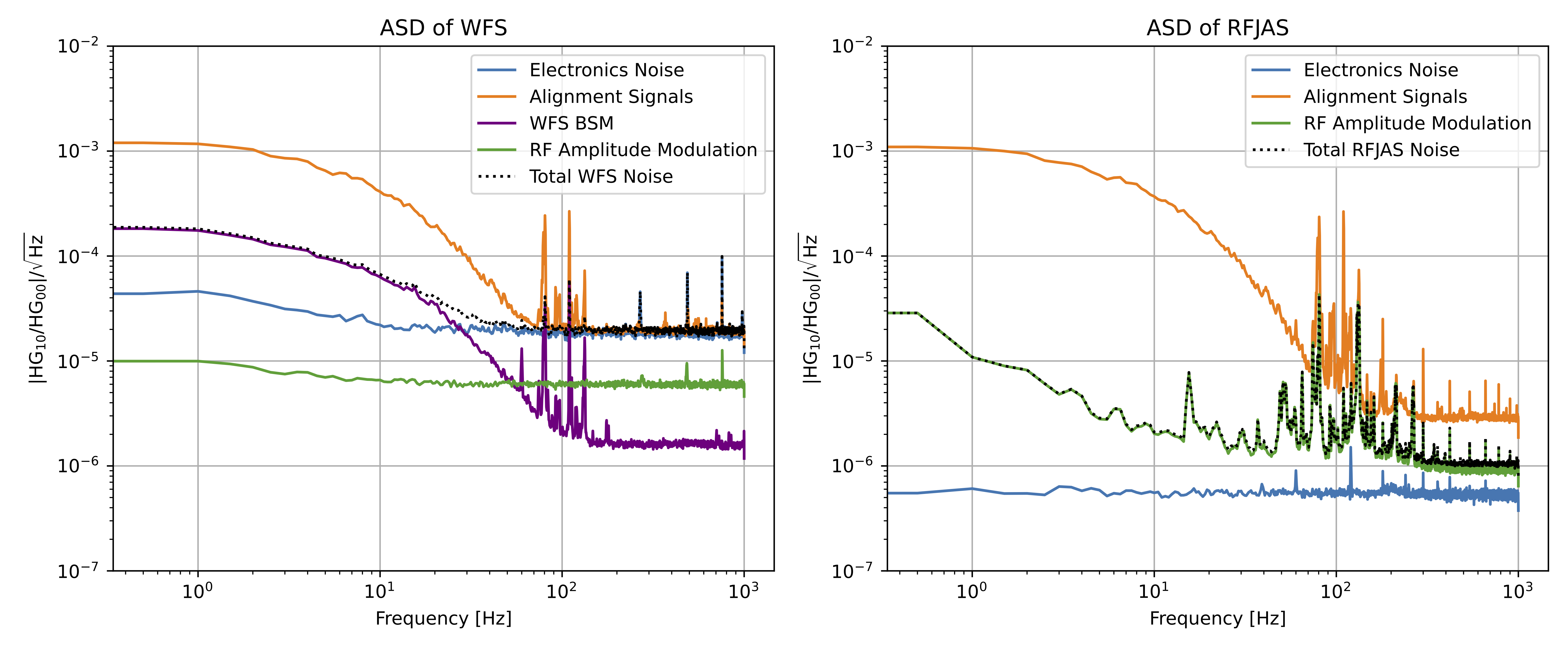
This work evaluates the performance of RFJAS through a direct, side-by-side comparison with WFS. Our results show that WFS performance is constrained by technical noise arising from beam spot motion (BSM), mainly due to beam miscentering on QPDs. In contrast, RFJAS is primarily limited by residual RF amplitude modulation. A blended scheme that combines both sensing methods may offer the most practical approach for use in gravitational wave detectors such as Advanced LIGO.
2. Optical Alignment for High-Precision Systems
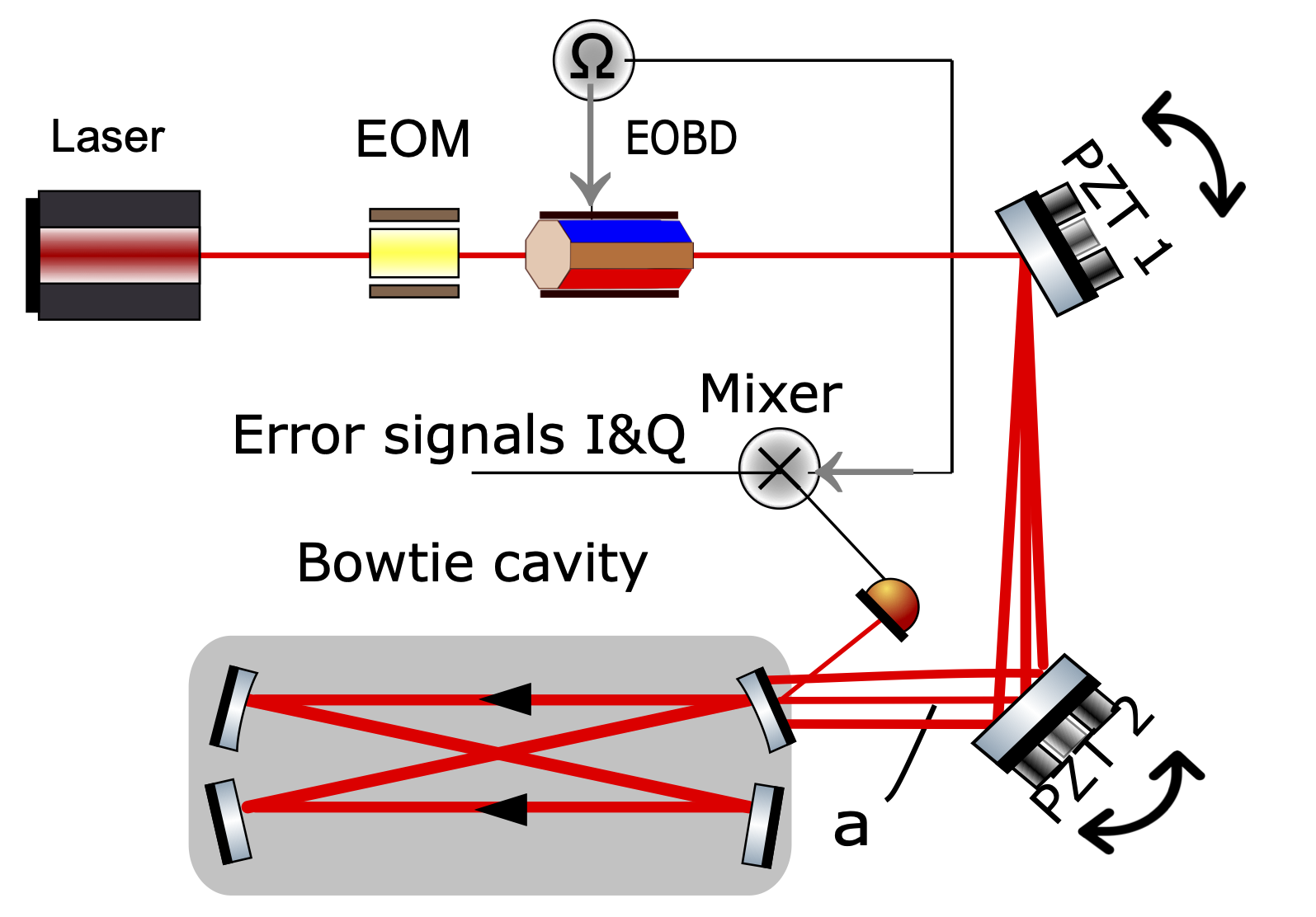
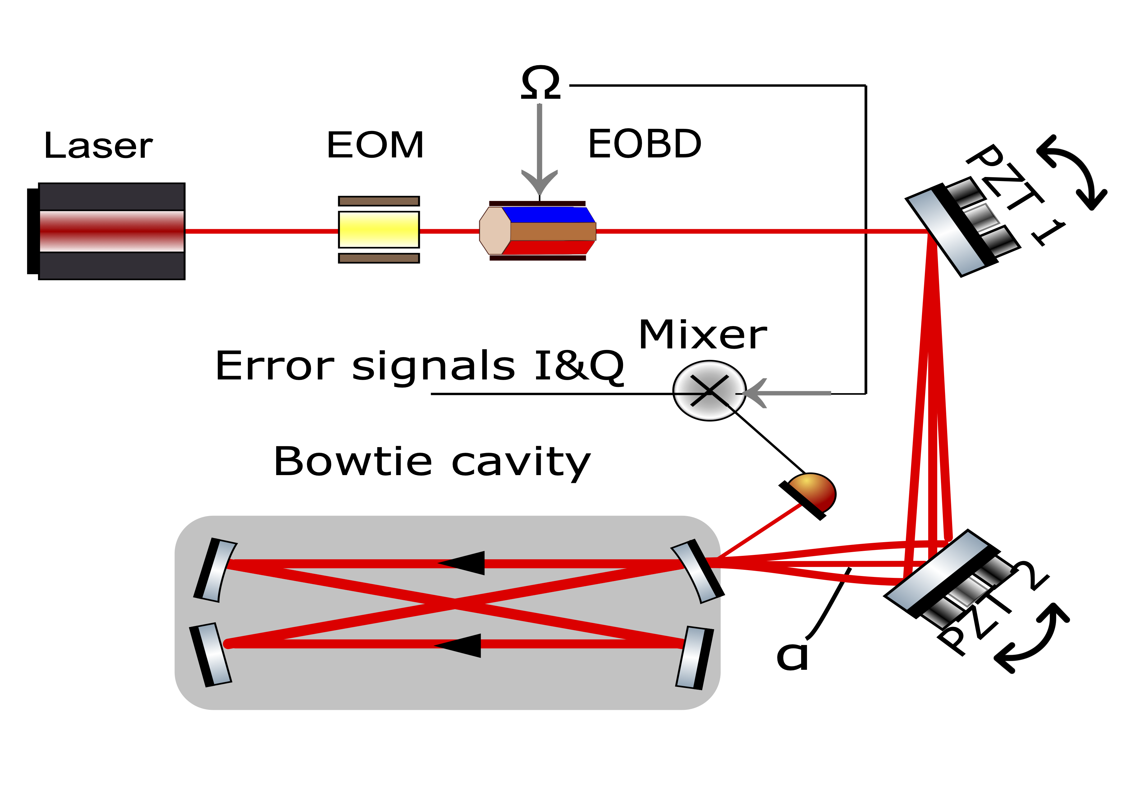
I investigate a new alignment sensing scheme for optical cavities named Radio Frequency Jitter Alignment Sensing Scheme (RFJAS). This scheme is proposed to work along with the currently used WaveFront Sensing Scheme. RFJAS relies on using an electro-optic beam deflector to generate first higher order modes (HOM) sidebands. These sidebands can be used to beat with first HOM from misalignment.
Demodulating this beat signal recovers full alignment of the optical cavity, when operating the correct modulation frequency. The tracking setup includes the laser source, the electro-optic beam deflector, 2 steering mirrors (PZT1 and PZT2), and the corresponding optical cavity loops.
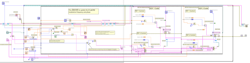
3. Automation of Optical Bench Using LabVIEW
Experimental lab setups involve tracking multiple instruments and hardware triggers synchronously. To make testing efficient, I utilized LabVIEW to automate the entire table-top experiment suite.
This system configures the modulation/demodulation frequency and phase profiles of the electro-optic beam deflector, drives the tilt alignment parameters using external function generators tied to high-speed piezo mirrors, and records photodiode reflection responses directly into clean datasets across iterative runtime sweeps.
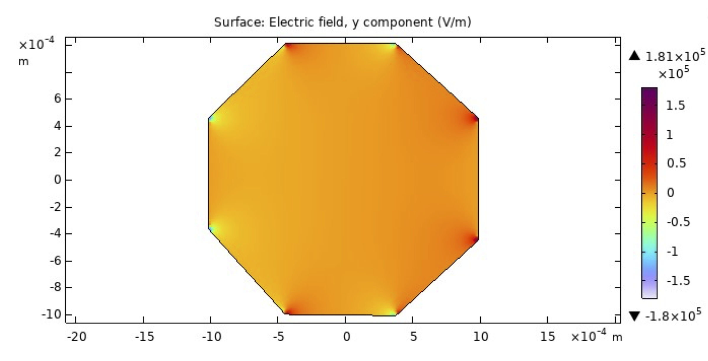
4. COMSOL Multiphysics Modeling
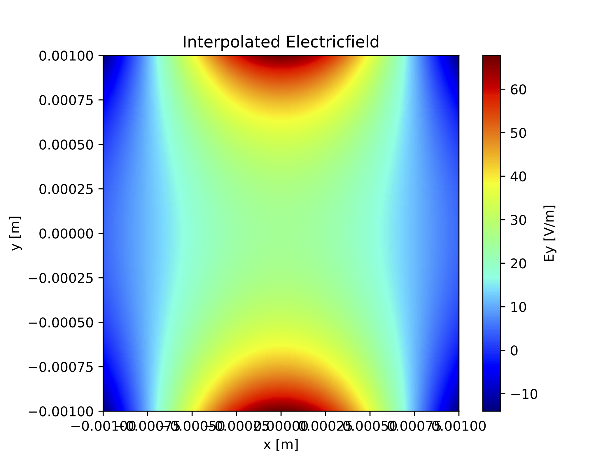
I used COMSOL to model finite element electrostatic indices within lithium tantalate (LiTaO3) crystals subject to varying radio frequency voltage configurations. This simulation cleanly map out spatial beam deflection profiles.
Figure 1 shows the electric field inside the crystal as simulated in COMSOL. While Figure 2 and Figure 3 highlight the electric field grids across custom electro-optic lenses (EOL) engineered for optical mode mismatch tracking loops.
5. Zemax Numerical Ray Tracing (Side Project)
As a side project to expand my structural knowledge of spatial laser constraints, I simulated complex Gaussian beam propagation across specialized multiple lens systems inside Zemax. This exploratory numerical modeling was instrumental in building spatial physical intuition for adjusting layout parameters, lens focal spacings, and beam curvature variables in the laboratory.